Spin: Simple Volume Control

Spin is a low cost USB volume/mute control device based on the Adafruit Trinket M0. It grew out of the need to have an easy to access volume control during long Zoom meetings. The outer piece is entirely free spinning, thanks to a rotary encoder. Spinning the dial left or right increments and decrements volume of a host computer and pressing down the dial mutes/unmutes the speakers. It can be built in under an hour with less than $20 of parts.
Features
- Variable speed The volume is incremented more as the dial is spun faster, allowing for easy control.
- Sized for easy use Spin is 2 1/8” (5.5cm) tall and 2.5” (6.3cm) across, it doesn’t take up much room but isn’t easily lost amongst desk clutter.
- Customizable The keys can be easily rebound to other Consumer Control codes, including play/pause, skip, and others.
Hardware
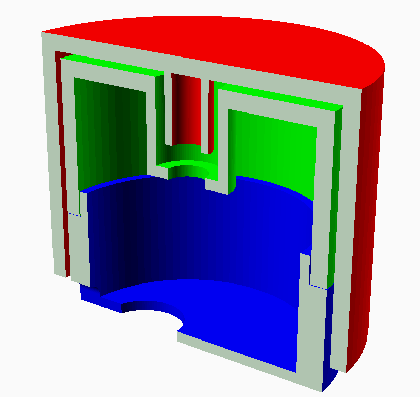
Spin’s brain is an Adafruit Trinket M0, running CircuitPython. The physical interface is a rotary encoder with integrated button, available cheaply on Amazon. The enclosure is made up of 3 3D printed parts.

Software
Spin works by emulating a USB HID device and using Consumer Control codes to send volume increment, decrement, and mute commands. It requires no drivers and should work under all operating systems, though it has only been tested with Windows 10. Also, as it runs CircuitPython, no toolchain is required and the device can be dynamically reprogrammed by editing the files within the emulated USB storage.
Materials
This can be built using parts you may already have on hand. Any CircuitPython compatible board can be used in place of the Trinket.
- 1x Adafruit Trinket M0
- 1x Rotary encoder with pushbutton
- 5x ~4” (10cm) pieces of flexible thin gauge wire
- 1 each of the 3D printed parts
- Miscellaneous: packing tape, thread lock, superglue or hot glue, and solder
Setup
- Print the 3 parts. STL files are provided in the
CADfolder, and an OpenSCAD file is available for those that want to modify the design. I printed the pieces in PLA with 20% infill, 0.2mm layer height, line supports, and a brim on a Creality CR-10. - Optional: Modify the encoder. I didn’t want the encoder to have detents, so I disassembled it and bent the detent springs flat. To do this:
- Bend out the tabs holding the outer metal case on.
- Carefully separate the layers and remove any remaining parts from the plastic case.
- There will be two D shaped springs molded into the plastic case, bend these back into the recess of the case.
- Reassemble the case and bend the clips back into place.
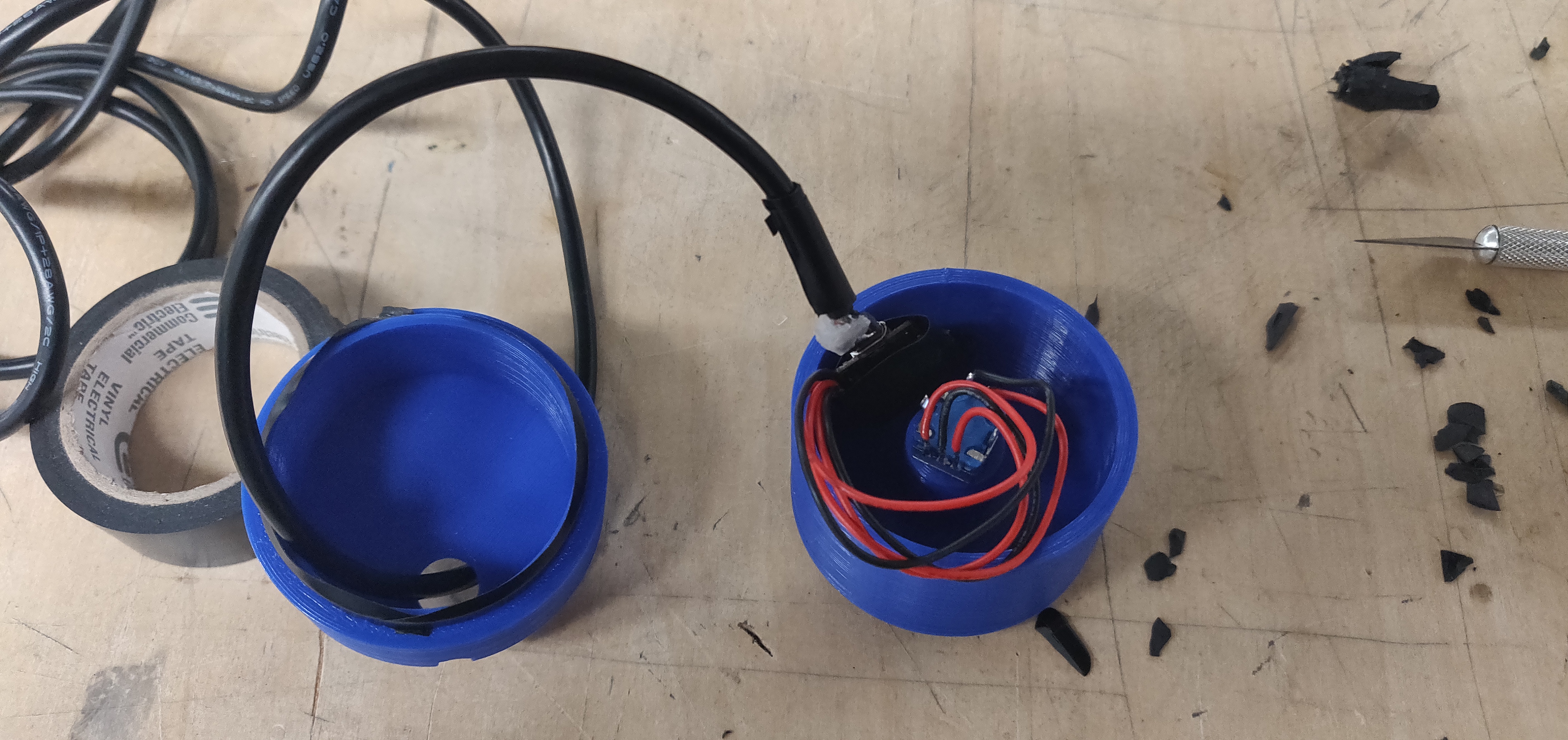
- Wire the encoder. I recommend using 5 pieces of fairly thing, flexible wire to connect the Trinket and encoder so that there’s room to maneuver all the components inside the case.
- Wire the button:
- Solder a wire between one of the pins on the two pin side of the encoder and GND on the Trinket.
- Solder a wire between the other pin on the two pin side and D2 on the Trinket.
- Wire the encoder:
- Solder a wire between the middle pin on the three pin side of the encoder and GND on the Trinket.
- Solder the two remaining wires from the two remaining pins on the three pin side of the encoder to pins D3 and D4. It doesn’t matter which pin on the encoder connects to which pin on the Trinket, the direction can be changed easily in the code if they’re reversed.
- Wire the button:
- Test the wiring. Connect the Trinket to the computer, and copy the
main.pyfile into the root directory of the Trinket’s drive. Try rotating the encoder’s knob, it should change the volume. Try pressing the button, it should mute and unmute the computer. If one of these doesn’t work, double check your wiring. If that doesn’t resolve it, open a serial terminal at 9600 baud and see if any error messages are given out when the board is reset. - Install the encoder. Add a drop of blue thread lock to the encoder threads to prevent it from coming loose. Push the encoder through the hole in the inside top piece. The encoder’s metal knob should be barely showing above the end of the hole. Slide one of the encoder nuts over the end of the encoder and use tweezers to screw it into place. To make sure it doesn’t move, use superglue or hot glue to fix the encoder in place from the back.
- Assemble the case. Thread the USB cable through the hole in the bottom piece. Optionally, you can tie a knot in the cable to prevent it from being pulled through. Plug the cable into the Trinket and fit it into the top of the case. If it doesn’t fit, try placing it at an angle and fitting the pieces together to see if it closes. Once the pieces fit together, run one layer of packing tape around the outside to hold the pieces together, or add tape as needed on the inside ring to keep the pieces firmly together.

- Final test. Plug it into the computer. If everything works, you’re done. If not, resolve any issues before putting on the top piece, as it’s difficult to separate once it’s in place.
- Final assembly. Finally, press the top piece onto the encoder knob, making sure to press straight down to not bend it.
Material sourcing
The only link that is important is the encoder link. I’m fairly sure it’s a generic Chinesium part, but that’s the exact product I used, so that’s the only one I know will fit (until they change the product).
For the USB cable, it’s helpful to have a right angle version to reduce bulkiness inside the case.
| Item | Source |
|---|---|
| Trinket M0 | https://www.adafruit.com/product/3500 |
| Encoder | https://www.amazon.com/gp/product/B07MW7D4FD/ |
| USB Cable | https://www.amazon.com/Cerrxian-Charge-Samsung-Motorola-Android/dp/B01N337FQF/ |
| 3D Printed Parts | STLs here: https://github.com/kk6axq/Spin/CAD/ |
| Misc (Wire, packing tape, glue) |
GitHub
All the project files are available on GitHub under a GNU GPLV3 license: https://github.com/kk6axq/Spin